Injection Molding DFM | Quality
How to Reduce Warpage and Sink Marks in Injection-Molded Lighting Housings
A practical guide to balancing wall thickness, ribs, gates, cooling, material choice, and inspection before production tooling is released.
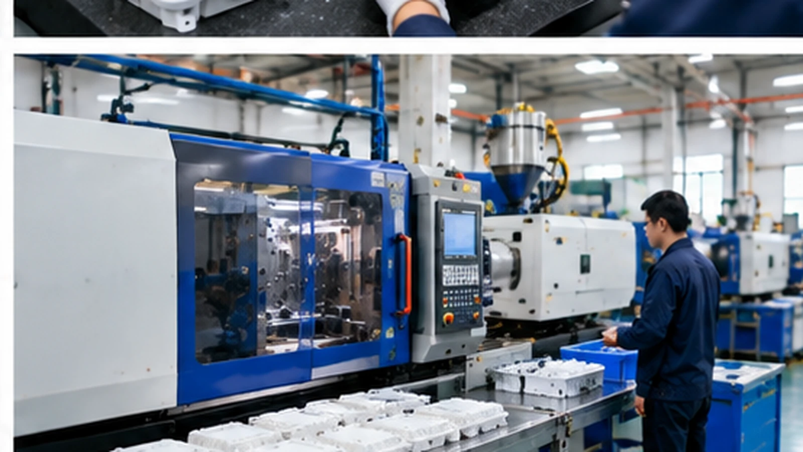
For a buyer sourcing lighting components, injection molded housing warpage is more than a cosmetic defect. A warped enclosure can create uneven lens fit, PCB interference, light leakage, sealing problems, assembly stress, and inconsistent gaps between mating parts. Sink marks can produce the same downstream frustration when ribs, bosses, or thick transitions pull the visible surface inward during cooling.
Why lighting housings are sensitive to warpage
Lighting housings often combine broad cosmetic faces with thin walls, internal ribs, screw bosses, clips, and openings for lenses or wiring. These features cool at different rates and can create uneven shrinkage. A housing may look acceptable on a flat table but fail when assembled against a lens, reflector, circuit board, gasket, or metal bracket.
The first step is to identify what matters most: a visible face, a sealing perimeter, a PCB datum, an optical interface, or a mounting plane. Those areas should drive the DFM discussion and inspection plan.
1. Control wall thickness and thick-to-thin transitions
Large changes in wall thickness increase the chance of uneven filling and cooling. Thick zones stay hot longer and shrink more than adjacent thin sections, which can create sink marks or pull a surface out of plane.
- Keep nominal walls as consistent as the function allows.
- Use a gradual transition when thickness must change.
- Core out heavy areas instead of leaving solid blocks.
- Review bosses and mounting pads for localized mass.
When the housing must be stiff, a balanced rib network is usually more predictable than simply increasing the outside wall. The correct wall and rib relationship depends on the chosen resin and the part geometry, so confirm the values in the supplier’s DFM review rather than applying a universal number.
2. Design ribs and bosses to reduce sink risk
Ribs and bosses are common sources of sink because they add material behind a cosmetic wall. They also influence how the part fills and how it is ejected. Place ribs where they provide structural value, keep their connection to the outer wall controlled, and avoid stacking several heavy features in one location.
Questions to ask during DFM
- Will the rib create a visible witness or sink on a Class A surface?
- Can the boss be cored or supported with a lighter feature?
- Does the feature need a draft angle for reliable ejection?
- Will an ejector pin or lifter land in a cosmetic or sealing area?
3. Use gate location to balance filling and appearance
Gate location affects flow length, pressure drop, weld lines, packing, fiber orientation in reinforced resins, and the position of visible gate marks. A gate placed too far from a thick region may leave that area under-packed; a gate feeding a broad face unevenly can contribute to differential shrinkage and distortion.
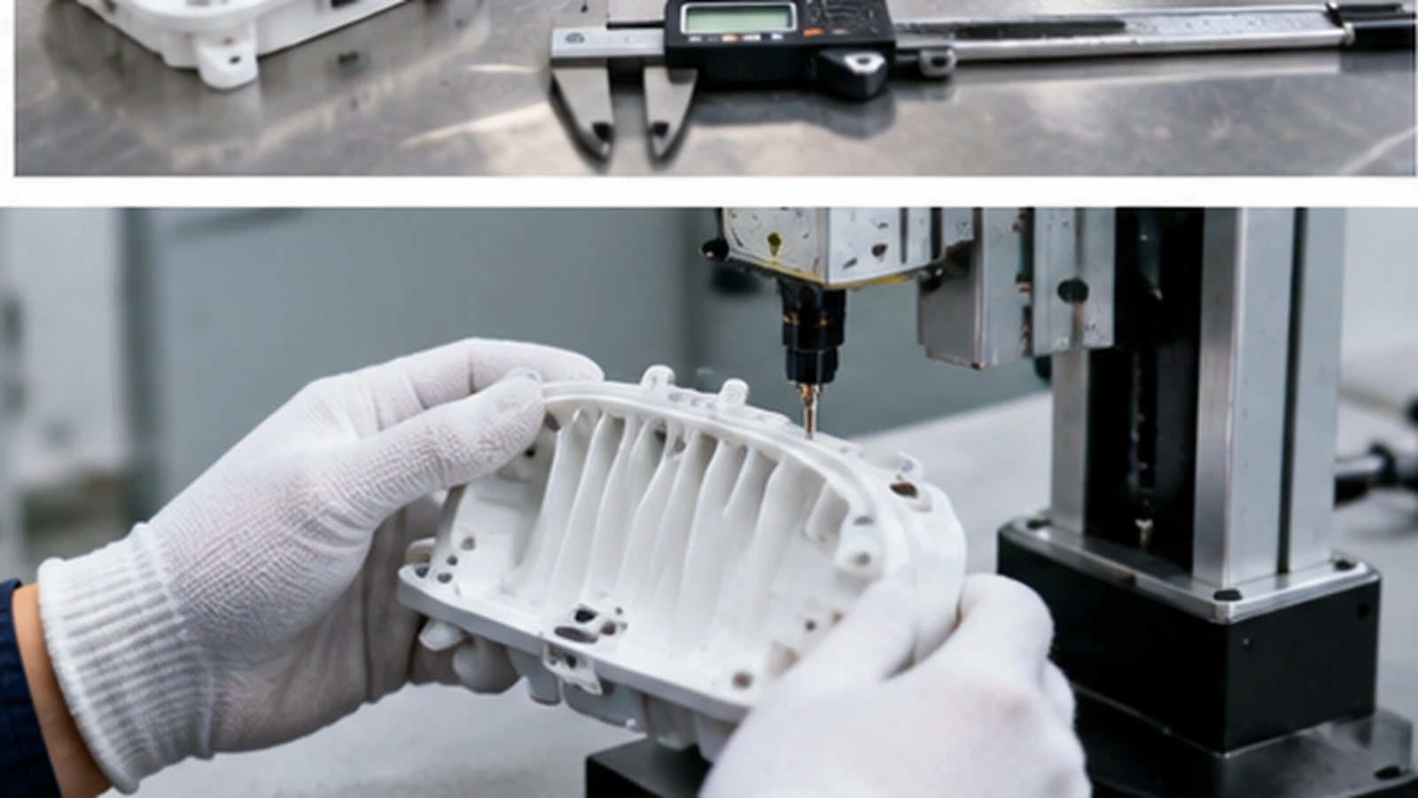
Ask the mold supplier to explain the proposed gate type and location, expected weld-line areas, and how the gate mark will be managed. This is why a dedicated review of gate design and gate location belongs in the tooling approval process.
4. Improve cooling balance in the mold
Uneven mold temperature is a frequent contributor to differential shrinkage. A broad housing may have one face or corner cooling faster than another, especially when the mold layout leaves some regions far from a cooling channel or forces channels around slides and inserts.
During the tooling review, ask how the supplier plans to cool:
- Large cosmetic surfaces and thick mounting zones
- Boss clusters, deep pockets, and areas around inserts
- Core and cavity halves with different heat loads
- Regions that may need baffles, bubblers, or conformal options
The goal is a balanced thermal plan that supports stable cycle conditions. A longer cycle can sometimes reduce distortion, but it should not be the only proposed solution.
5. Match resin behavior to the housing requirement
Different plastics have different shrinkage, flow, moisture sensitivity, heat resistance, and dimensional behavior. A material change made after tooling can alter the way the housing fills and shrinks. If the design may use PC, ABS, PC/ABS, a flame-retardant grade, or a reinforced resin, the RFQ should identify the approved options before the mold is finalized.
For a structured comparison, see the plastic enclosure materials guide. Confirm the resin data, drying requirements, color system, and any restrictions on regrind with the supplier’s quality team.
6. Separate cosmetic limits from functional tolerances
Not every surface needs the same acceptance standard. A hidden inside wall may tolerate a small witness that would be unacceptable on a visible lens surround. Define cosmetic zones, assembly interfaces, and measurement datums separately.
For production parts, specify:
- Flatness or profile requirements for mounting and sealing surfaces
- Fit and gap requirements at the lens, PCB, or mating enclosure
- Allowed flash, flow marks, sink, weld line, and color variation by zone
- Measurement method, fixture or datum scheme, and sample quantity
Use the injection molding tolerance guide to make the drawing more specific without over-tolerancing noncritical features.
7. Plan inspection around assembly risk
A visual check alone may miss a housing that is slowly pulling out of plane. A stronger inspection plan combines visual review with dimensional checks on the surfaces that determine assembly. Depending on the part, this can include a flatness check, profile measurement, go/no-go fixture, CMM inspection, or trial assembly with the lens and PCB.
Before approving samples, agree on which features will be measured, how the part will be supported, and whether the inspection is performed in a free state or an assembly fixture. Ask for photos and a report that clearly links results to drawing dimensions.
DFM questions to resolve before mold release
| Risk | Question for the supplier | Evidence to request |
|---|---|---|
| Sink | Where are the thick zones and how will they be packed? | DFM markup and sample photos |
| Warpage | How are flow and cooling balanced across the housing? | Mold layout, process plan, and dimensional report |
| Cosmetics | Which areas have different appearance limits? | Approved sample or visual standard |
| Assembly | Which datums and checks confirm fit with the lens and PCB? | Fixture or trial-assembly record |
Frequently asked questions
Can process settings alone eliminate warpage?
Sometimes a process adjustment reduces the symptom, but a design or cooling imbalance may remain. If the distortion returns when resin, cycle, or ambient conditions change, revisit the part and mold design rather than relying on one setting.
Should I change the material to solve sink marks?
Material behavior matters, but changing resin can affect appearance, strength, shrinkage, and compliance. First identify the thick feature and packing or cooling limitation, then compare approved material options with the supplier.
When should warpage be checked?
Check it during first-off sampling and again after process stabilization. Measure the surfaces that control assembly, and document the support condition so results from different samples are comparable.
Need a DFM review for a lighting housing?
Share the CAD model, drawing, resin preference, cosmetic zones, and assembly interfaces. Our injection molding team can review wall thickness, ribs, gates, cooling, tolerances, and inspection points before tooling is finalized.